To calculate thermal expansion in a pipe, you need the pipe material, the length of the straight section and the change in pipe metal temperature from the reference condition. These inputs give the free change in length. To assess actual movement, support reactions and loads at equipment connections, you also need the routing and restraint details.
How do you calculate free thermal expansion?
Multiply the average coefficient of linear thermal expansion for the material and temperature range by the pipe length and the temperature change. This provides a preliminary estimate when the temperature change is approximately uniform along the section.
ΔL ≈ α × L × ΔT. ΔL is the change in length, α is the average coefficient of linear thermal expansion, L is the straight pipe length at the reference temperature and ΔT is the final pipe metal temperature minus the reference temperature. Using mm for L, 1/°C for α and °C for ΔT gives an answer in mm. A negative ΔT indicates contraction.
Worked example. The metal temperature of a 20 m straight pipe section rises from 20 °C to 170 °C. If the assumed coefficient is 12 × 10⁻⁶ 1/°C, ΔT is 150 °C and the free expansion is 12 × 10⁻⁶ × 20,000 × 150 ≈ 36 mm. For project calculations, use verified data for the actual material grade and temperature range.
Which temperatures and lengths should you use?
Use the pipe metal temperature at installation or at the reference condition defined for the analysis. Use the metal temperature for the operating case as the final value. If you use the fluid temperature as a proxy for the pipe metal temperature, document that assumption. Record separate temperatures for startup, normal operation and shutdown where they differ.
For a route with changes in direction, record each straight length with its orientation. Mark bends, offsets, branch connections and elevation changes on the isometric. Assess sections separately where the material or temperature changes. The piping isometric guide shows how to check dimensions and route direction on the drawing.
How do supports and equipment connections affect the result?
Anchors, guides and supports determine which directions the pipe can move in. The calculated free expansion gives the change in length of an unrestrained section. Equipment nozzle displacement depends on end movements, restraint gaps, sliding surfaces, friction and pipe geometry.
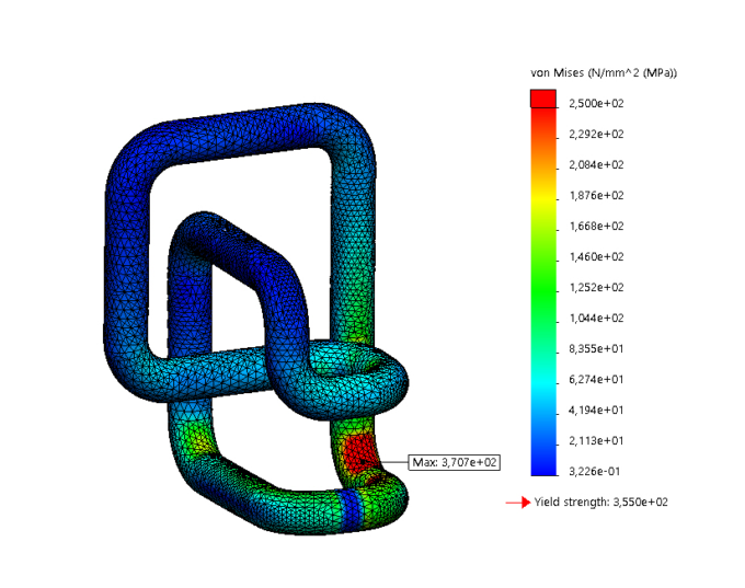
A bend or offset can add flexibility to a route. A straight section restrained at both ends can transfer thermal loads to its anchors and end connections. Pipe stress analysis compares calculated movements, support loads, and the forces and moments at equipment nozzles with the applicable acceptance limits.
What data should you collect for pipe stress analysis?
Gather the current piping isometric and equipment layout along with the data below. At an existing site, check that the drawings match the actual locations of supports, guides and connections.
Data group | What to collect |
|---|---|
Routing | Straight lengths, elevations, elbows, offsets, branches and equipment connections |
Pipe and contents | Material grade, outside diameter, wall thickness, fluid and insulation details |
Operating conditions | Reference metal temperature, hot and cold cases, and the corresponding pressures and temperatures |
Supports and anchors | Locations, restrained directions, gaps and friction data where available |
Equipment and acceptance criteria | Nozzle movements, allowable forces and moments, and cycle count where relevant |
When should you consider an expansion joint?
If the route’s flexibility cannot accommodate the expected movements and connection loads, assess rerouting, an expansion loop or an expansion joint. When evaluating an expansion joint, provide the expected axial, lateral and angular movements, as well as operating pressure, temperature and cycle count. Assess anchors, guides and pressure thrust as part of the joint arrangement.
Conclusion
Start with the material, pipe length and metal temperature change. Add the restraint layout and nozzle limits to assess where movement will be taken up and what loads reach the equipment. Share the project data through ThermoX’s pipe stress analysis service.
Frequently Asked Questions
Can I calculate thermal expansion from the fluid temperature?
Use the pipe metal temperature for the relevant operating case. If the fluid temperature is used as a proxy, document that assumption and review it where heat loss or transient conditions can change the metal temperature.
Does 36 mm of free expansion mean the equipment nozzle moves 36 mm?
36 mm is the free change in length for the example section. Actual nozzle movement and loads depend on the pipe route, restraints and equipment movements.
Does every hot pipe need an expansion joint?
A route may accommodate the expected movement through its geometry and supports. Consider an expansion joint or another layout when the calculated movements and loads exceed the project’s applicable limits.