A piping isometric shows a pipe route, changes in direction, dimensions and connections on a single drawing. When preparing for spool fabrication, it is important both to follow the drawing from start to finish and to check that the accompanying bill of materials and connection details belong to the same revision. The sequence below explains where to start when opening a drawing for the first time and what to verify before releasing it for fabrication.
Where Should You Start Reading a Piping Isometric?
The drawing number and revision are usually in the title block. First compare the drawing number, line number, sheet number and revision against the work package record. If a line spans several sheets, note the sheet or drawing referenced by each continuation symbol. Check the project document register to confirm that the drawing is approved for fabrication, rather than relying on the revision code alone.
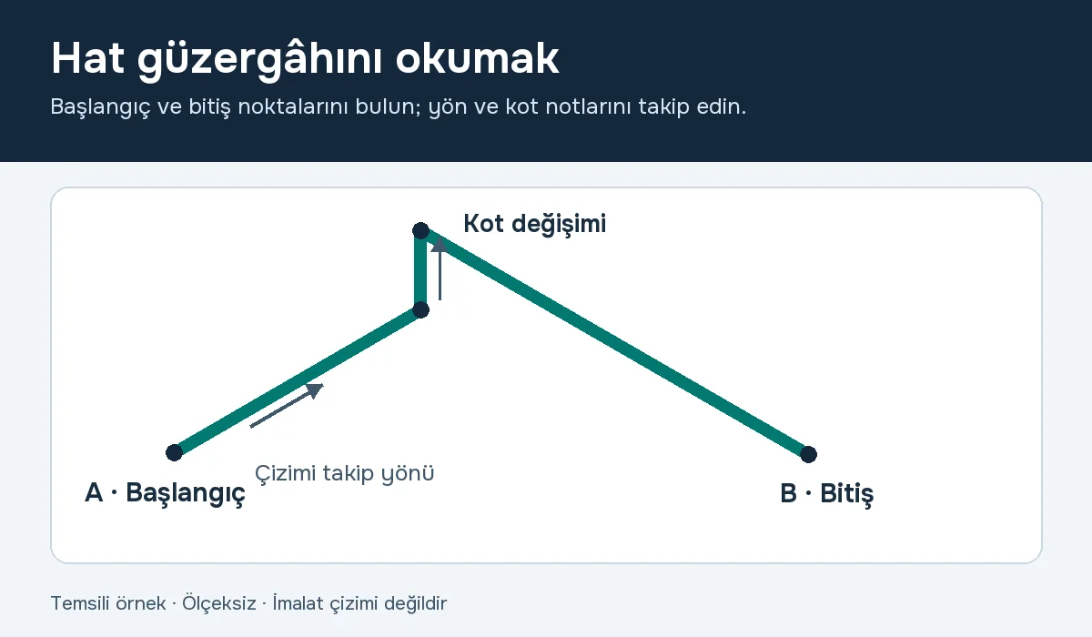
Next, identify the start and end points of the line. These may be an equipment nozzle, a tie-in to an existing line or a line end continued on another drawing. Direction markers, coordinates and elevations help establish the line's position in the plant. When examining several lines or sheets together, noting connection references helps avoid confusing two similar lines.
Read the drawing notes at this stage too. They may specify units, the reference elevation and which detail drawings to consult. If information is missing or two documents for the same line conflict, you can continue reading, but clarify which information governs before releasing the affected component for fabrication.
How Do You Follow the Route, Dimensions and Symbols?
Starting at a connection point, follow the route component by component. Identify the elbow after the straight pipe, any branch and the connecting flange in order. An elbow that changes horizontal direction is different from one that changes elevation. Direction references and elevation notes help distinguish them.
Consult the drawing or project legend for elbow, flange and weld symbols. The Turkish Ministry of National Education's Piping Isometrics module provides an introductory reference for symbols and spool drawings. Use the project legend when interpreting your actual drawing. For example, if a connection symbol distinguishes shop welds from field welds, confirm which symbol denotes each type in that drawing's legend.
Do not derive dimensions from the length of a line on the drawing. Check which two references the stated dimension spans: pipe centreline to centreline, flange face to flange face or another reference. Confusing an overall distance with a component dimension can produce different lengths from the same drawing. If the start and end references are unclear, flag the detail and consult the project team.
In an illustrative example, the line starts at connection A, changes elevation through an elbow and ends at connection B. Start at A, follow the direction change and verify the mating equipment's connection reference at B. This sequence is independent of the angle at which the drawing appears on the page.
How Are Spool Boundaries Identified on a Drawing?
The spool number or reference identifies the section of a line treated as a single fabrication assembly. The line number may identify the entire line, while the spool reference identifies part of it. If a line contains several spools, check each assembly's start and end connections on its own drawing.
Do not determine a spool boundary solely from the nearest elbow or flange. A connection may belong to equipment, an adjacent spool or a joint to be completed on site. Read any separate spool drawing or connection detail alongside the main isometric. For spool fabrication, this clarifies which components go into the workshop and which connections require field verification.
Even if points A and B both appear on the drawing, do not assume that every component between them belongs to the same assembly. If the spool reference is unclear, verify component allocation against the approved drawing or work package.
How Do You Compare the Isometric Drawing and Bill of Materials?
The bill of materials helps check whether the components shown on the drawing are correctly specified for fabrication. First verify that the list matches the same drawing and revision. Then compare the component tags on the drawing with the listed items. No numerical values are provided in the example below; use your project's approved data.
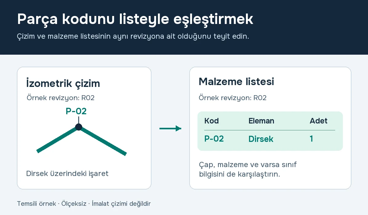
Drawing Item to Check | Information to Compare |
|---|---|
Pipe and component tag | Item code, nominal diameter and material description in the list. |
Elbow and fitting | Component type, size, class where applicable, and quantity. |
Flange and connection end | Flange type and class in the list; orientation and position on the drawing and relevant detail. |
Spool reference | Whether the material item belongs to the specific spool or the entire line. |
For example, a flange's type and quantity may be correct in the list while its orientation is specified only in the layout or connection detail. Do not use the list to confirm orientation in that case. Likewise, matching quantities do not confirm the material class. If there is a conflict, record the drawing number, revision and affected item together, and let the responsible team determine which document needs correction.
Checklist Before Release for Spool Fabrication
The pre-fabrication checklist makes discrepancies between drawings and material lists visible before work reaches the workshop. Assess field connections together with the layout and connection information for process piping fabrication.
Do the drawing number, sheet and revision match the document register approved for fabrication?
Are line and spool references and start and end points clear?
Are units, direction, elevations and dimension references legible?
Do item codes, diameters, material specifications and quantities match the list?
Have flange orientations and field connections been verified against the relevant drawing or detail?
Has a technical clarification record been opened for missing dimensions and conflicting documents?
When you find a discrepancy, make the question specific: “Which two references does this dimension span?”, “Which detail applies at connection B?” or “Which spool does this material item belong to?” Include the drawing number and revision. To discuss your project's spool scope, you can share the approved isometric, bill of materials and unresolved connection points with the ThermoX team.
Conclusion
Before releasing a piping isometric for fabrication, check the approved revision, connection points and stated dimensions. Then compare item codes and quantities against the bill of materials and verify installation information such as flange orientation from the relevant drawing. If a dimension is unclear or records conflict, obtain confirmation from the project team before releasing the component for fabrication.
Frequently Asked Questions
Can dimensions be measured with a ruler on a piping isometric?
No. Use the stated dimensions and the two references they span. If a dimension is missing or unclear, obtain confirmation from the project team before fabrication.
What is the difference between a line number and a spool number?
The line number identifies the piping line, while the spool number identifies a section defined as a separate fabrication assembly. One line may contain several spools.
Can flange orientation be determined from the bill of materials?
The bill of materials may contain flange type, class and quantity. Verify orientation and connection position from the isometric drawing or relevant connection detail.
What should be done if the drawing and bill of materials conflict?
First check that both documents belong to the same approved revision. If the discrepancy remains, record the drawing number, revision and affected item code. Do not release that component for fabrication until clarification is received.