An economizer is a heat exchanger that transfers part of the heat in flue gas to boiler feedwater. Warmer feedwater reduces the heat that must be added inside the boiler to produce steam at the same operating conditions. In a steam plant, its main purpose is to use some of the energy that would otherwise continue towards the stack.
Understanding an economizer on a process diagram involves following two streams. One is the hot flue gas leaving the boiler. The other is the feedwater travelling towards the boiler. This guide explains their relationship, the basic equipment arrangement and the differences between an economizer and other boiler auxiliaries.
What does a boiler economizer do?
A boiler economizer preheats feedwater using recovered heat. Part of the energy needed between the incoming water condition and the required steam condition can therefore come from the flue gas. The contribution depends on the temperatures and flow rates available on both sides of the equipment.
For example, a plant with a changing production load may have different flue-gas flows and feedwater requirements throughout the day. The annual benefit must be assessed against those operating conditions. A fixed saving percentage cannot describe every installation. Measurements should represent the way the plant actually operates.
In a typical boiler feedwater application, the purpose is to heat water before it enters the boiler. The required outlet condition and the permitted operating range are determined as part of the connected system design. The presence of an economizer alone does not define how much useful heat can be recovered.
Where is the economizer installed in a steam system?
On the gas side, an economizer is installed in the flue-gas path downstream of the main boiler heating surfaces. On the water side, it is connected to the feedwater circuit before the water enters the boiler. Its exact location depends on the boiler and auxiliary equipment arrangement.
In a simplified flow diagram, hot gas first contributes to steam generation inside the boiler. It then passes through the economizer, where more heat is transferred to water. The cooler gas continues to downstream equipment or the stack. The heated feedwater continues into the boiler circuit.
Identifying the gas inlet, gas outlet, water inlet and water outlet makes an arrangement drawing easier to read. These four points show the two streams involved and the connected pipework or ductwork. Their directions should always be taken from the equipment design rather than assumed from its external appearance.
How does an economizer work?
An economizer uses the temperature difference between hot gas and cooler water. In a tubular arrangement, heat passes from the gas to the outside of the tube, through the tube wall and into the water. Each fluid remains within its own flow path during normal operation.
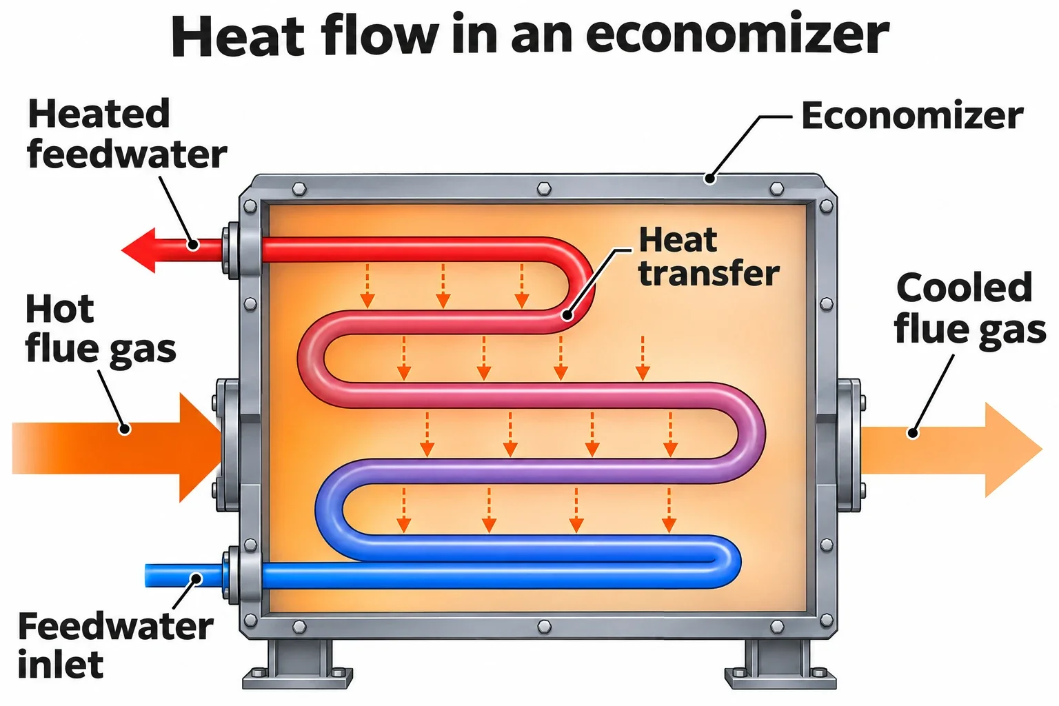
In a conventional tubular boiler economizer, water flows inside the tubes and flue gas passes around them. Mixing the two streams is not the intended process. Tube geometry, surface arrangement and material are selected by considering the operating conditions of both circuits.
Hot gas enters the equipment. The flue gas leaving the boiler reaches the economizer gas passage.
Heat crosses the transfer surface. Some of the gas energy passes through the tubes into the feedwater.
Warmer water leaves. The feedwater carries the recovered energy towards the boiler.
Cooler gas continues downstream. Its outlet condition must remain within the accepted limits for the installation.
This sequence explains the process, but the amount of heat transferred varies with operating conditions. Changing flow rates, inlet temperatures and deposits on the heating surfaces affect the useful heat delivered to the water.
What are the main economizer components?
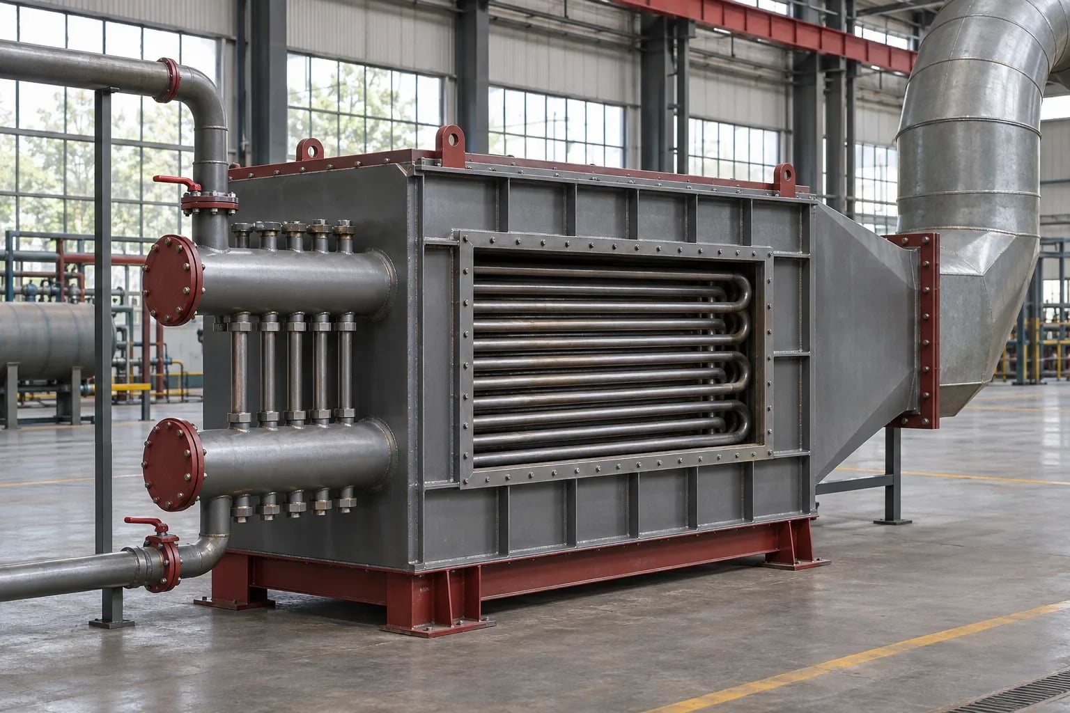
A tubular economizer combines heating surfaces, water distribution components and a casing that directs the gas. The size and arrangement of these parts are established through the engineering design for a particular installation.
Component | Main function |
|---|---|
Tube bundle | Provides the surface through which heat passes from gas to water. |
Inlet and outlet headers | Distribute water to the tubes and collect the water leaving them. |
Gas casing and connections | Guide flue gas through the region containing the heat transfer surfaces. |
Supports | Carry the equipment and accommodate the movements allowed for in its design. |
Cleaning and maintenance access | Allow inspection of the surfaces and access for planned maintenance. |
Instrument connections | Allow the specified temperatures and pressures to be monitored. |
Equipment terminology can vary between projects. When a drawing refers to a coil or bundle, the associated component and its boundaries should be checked. A replacement heating surface assembly and a complete economizer casing may represent different supply scopes.
How do finned-tube, bare-tube and stainless steel economizers differ?
Finned-tube and bare-tube describe the geometry of the heating surface. Stainless steel describes a material group. These terms therefore describe different characteristics, and a material choice can be combined with a particular tube geometry.
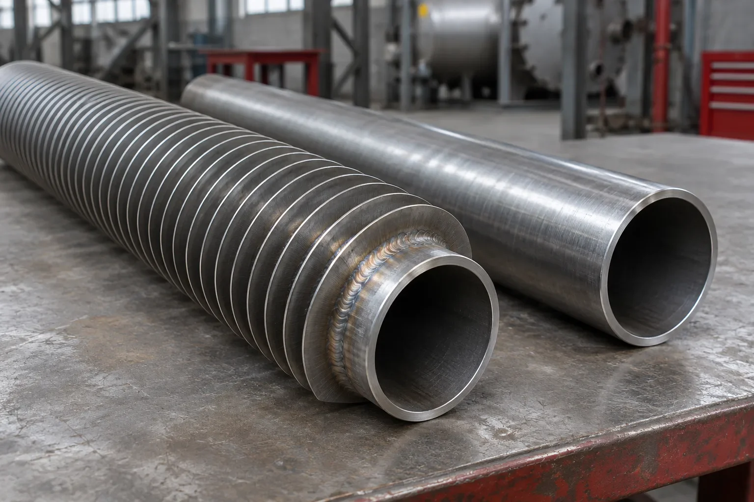
Fins add external surface area on the gas side. A bare tube is used without these additional fins. Selection involves more than comparing surface area. Dust loading, deposit formation and the proposed cleaning method also influence the arrangement.
Stainless steel selection depends on the gas and water chemistry, temperatures and any expected condensation. The material name alone does not establish suitability for every corrosive environment. The available equipment options and manufacturing scope are described on the economizer systems page.
How is an economizer different from an air preheater or superheater?
The main distinction is the fluid being heated. A boiler economizer heats feedwater, an air preheater heats combustion air and a superheater adds heat to steam that has already been generated. Following the inlet and outlet streams on a diagram helps distinguish these functions.
If water enters a unit and warmer water leaves, the duty is water heating. If steam enters and leaves at a higher temperature, the duty involves superheating. Equipment that raises the temperature of combustion air serves the air circuit. These functions can be present together in the same boiler plant.
A waste heat boiler can also have a different role from a feedwater economizer. It may use process gas energy to generate steam or hot water. A feedwater economizer preheats water for the boiler circuit. The names should be read together with the actual duty shown on the process diagram.
Where can an economizer be considered?
An economizer can be assessed where flue gas at a useful temperature is available at the same time as a water stream that can absorb the recovered heat. Plants with continuing steam demand and projects to improve existing boilers are typical situations for this assessment.
The first questions concern operating hours and when the recovered heat can be used. A high stack temperature alone is insufficient to determine annual benefit. Water demand must also be present while the hot gas is available.
Condensate return and feedwater temperature influence the available duty. Two boilers with the same nominal steam capacity may consequently produce different results from an economizer. The wider engineering considerations are discussed in the waste heat recovery guide.
Which operating values should be monitored?
An economizer is assessed by considering gas and water inlet and outlet temperatures together with flow and pressure information. Comparing measurements at similar boiler loads makes changes easier to interpret.
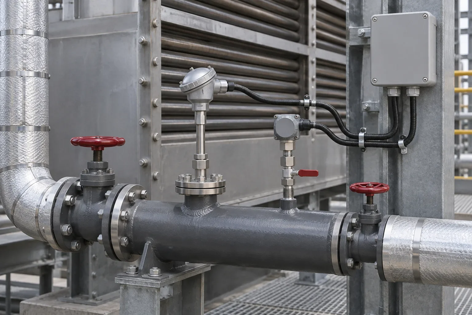
A single rising or falling temperature does not establish an equipment fault. A change in production load may have changed both gas and water flows. Instrument condition, measurement location and the cleaning history should be considered alongside the operating record.
Conventional and condensing arrangements also have different accepted gas outlet conditions. Whether condensation forms part of the design must be considered together with suitable materials and arrangements for handling the condensed liquid. A universal outlet temperature is therefore unsuitable for describing all plants.
From understanding the equipment to assessing the installation
Identifying an economizer involves checking the two streams it connects, their flow directions and the conditions recorded during operation. This establishes the equipment duty and its relationship with the existing plant.
A preliminary review can use the current process diagram, gas and feedwater information and maintenance history. Where damaged tubes or replacement work are involved, the economizer coil tube replacement guide explains the related maintenance scope.
Frequently Asked Questions
Are economizer and economiser the same equipment?
Economizer and economiser are alternative spellings for the same equipment. Its specific duty should still be checked from the heated fluid, the gas source and the operating conditions shown in the project documentation.
Does a boiler economizer mix flue gas with water?
In a conventional tubular boiler economizer, gas and water remain in separate flow paths. Heat passes through the tube surface. Mixing the two streams is not the intended operating process.
Does an economizer deliver the same fuel saving on every boiler?
No. Gas and water flows, temperatures, boiler load, operating hours and surface condition affect the heat available for recovery. Fuel savings require a separate calculation based on the plant data.
Is a stainless steel economizer always a condensing economizer?
Stainless steel construction alone does not establish that an economizer is designed for condensing operation. A condensing application also requires assessment of gas composition, temperatures, material suitability and the collection and drainage of condensate.
Can an economizer be added to an existing boiler?
An economizer retrofit can be assessed through an engineering review. The gas path, available fan capability, permitted pressure loss, feedwater circuit and space for installation need to be considered together.